Martyna is a software developer with a passion for programming, automation, and innovation. Currently working for the global corporate IT consulting sector, she is a new-generation techie who hails from Warsaw University of Technology, Poland. She has certifications in both database administration and Java development. Her interests include creating small automation devices using embedded systems and various electronic components. In her free time, she practices yoga, which helps her to center her thoughts and come up with new ideas.
Read this article to find out how to create an ER diagram for hospital management systems.
Commonly, we start the database creation process by designing a logical database diagram. This diagram is a visual representation of the entities in a system and the relationships between them. Later in the process, the logical diagram is transformed into a physical database diagram that incorporates database-specific details.
In this article, we’ll walk you through building an entity-relationship diagram (ER diagram or ERD) for a hospital management system. First, we’ll introduce ER diagrams and the general rules for database modeling. Next, we’ll create the database model using the Vertabelo data modeler. This process consists of the following steps:
Let’s get started.
An ER diagram is a database model that illustrates entities (such as objects, people, or concepts) with their attributes (such as name, type, or age). Entities can be linked with one another; the nature of these links, or relationships, depends on how entities interact.
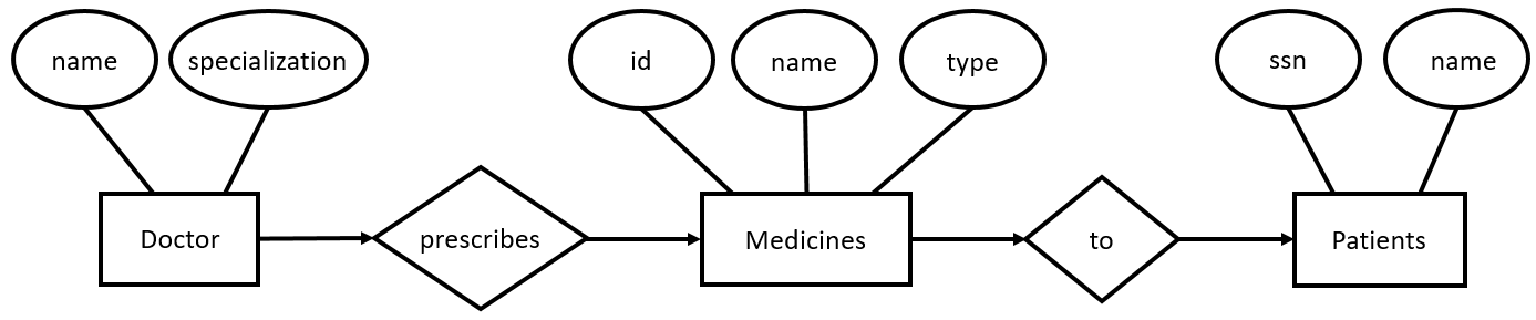
Here is a simple example of an ER diagram:
Let’s analyze it briefly. We’ve got three entities:
The relationships between the entities indicate that a Doctor prescribes Medicines to Patients.
This ER diagram presents a real-world scenario where a doctor of a particular specialization prescribes certain medicines to a patient.
There are different types of ER diagrams. The most widely used are conceptual, logical, and physical database models, which add some abstraction layers on top of the ER diagram presented above.
The process of database modeling involves people from different domains – such as database designers, data modelers, business stakeholders, and potential system users.
The first step in the process is to define data requirements using the conceptual database model, which is database independent. The conceptual model is very high-level and is the model shared with business (i.e. non-technical) stakeholders.
Next, we translate the conceptual model into the logical database model. This model details the structure of the data. Finally, the logical database model is transformed into the physical database model that outlines the tables’ structure and considers performance and storage details for a specific database engine.
Let’s go over some essential rules for database modeling:
These are the most basic data modeling rules; you can check out our article on data modeling basics or view the database modeling topic on our blog to learn more.
Now that we’ve gone through the core principles of data modeling, let’s begin on our hospital management system ERD. We’ll start by creating a logical database model.
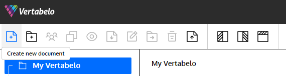
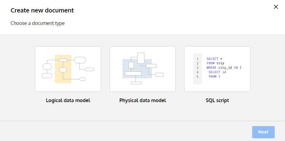
Here is how to create a logical data model in Vertabelo:
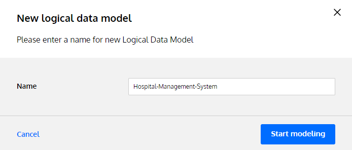
Now you’re ready to start modeling.
Let’s first identify all relevant entities:
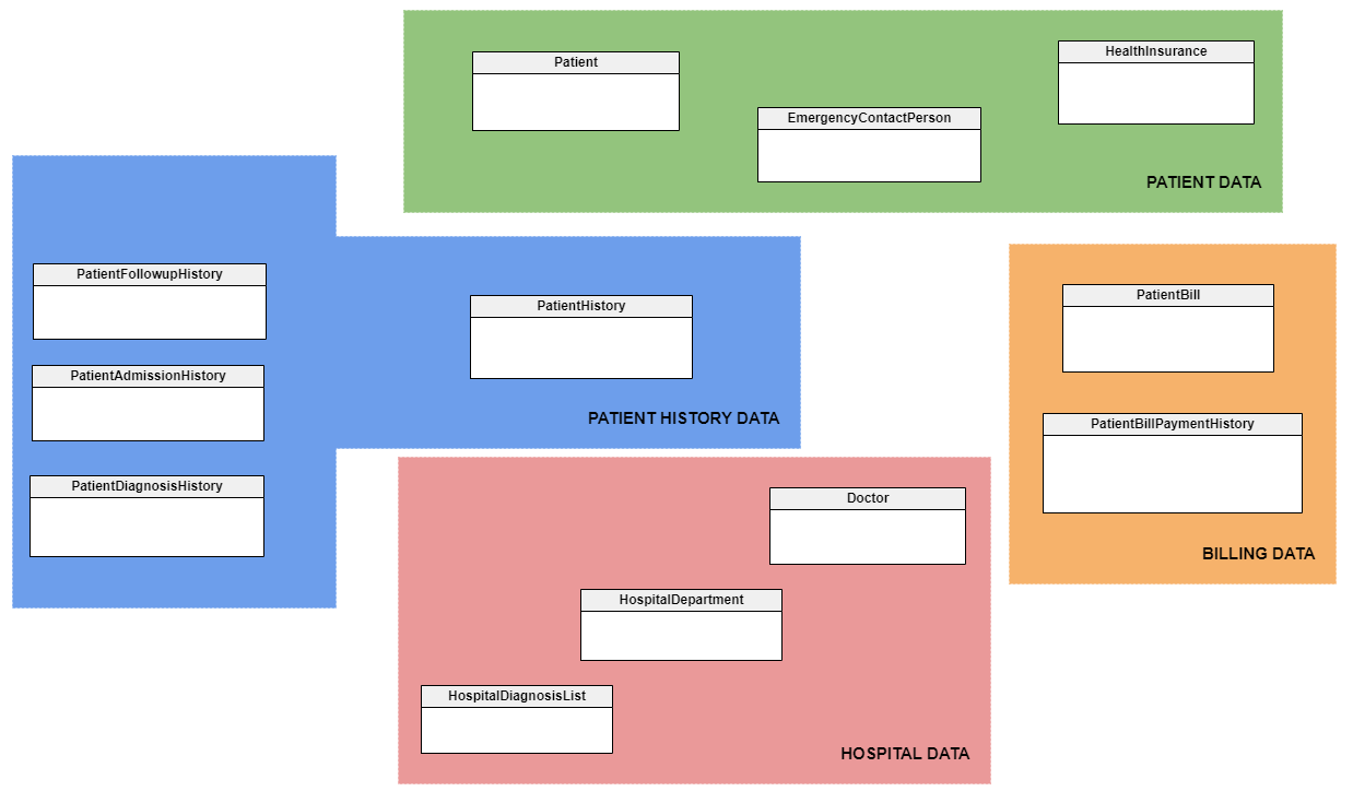
You’ll notice that we’ve also defined subject areas (PATIENT HISTORY DATA, HOSPITAL DATA, etc.) in various colors. Subject areas are a convenient way to see which tables share related data. You can add both subject areas and text notes from the left pane menu. To improve the readability of your database model, we encourage you to use subject areas and text notes.
You can create entities in Vertabelo by selecting the Add new entity button.
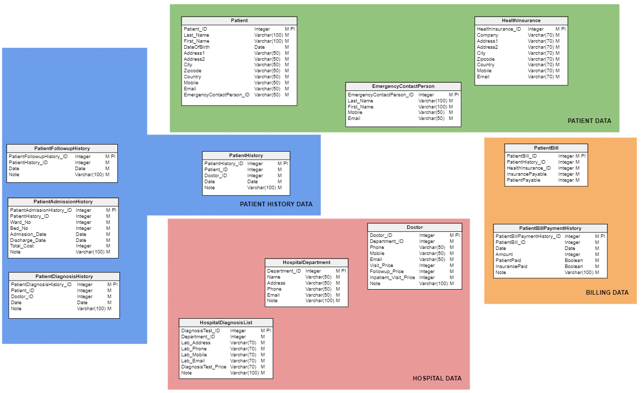
Next, we assign attributes to each of the entities. Attributes describe details or traits for each entity. For example, the Patient table includes attributes for a patient ID number that’s unique to each patient, the patient’s first and last names, their address, date of birth, and so on.
You can assign attributes to entities in Vertabelo by selecting an entity and clicking on the Add attribute button in the right pane.
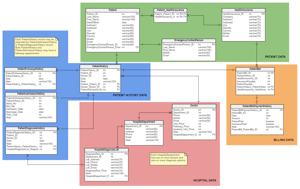
Finally, we define the relationships between the entities, including cardinalities. Here is the resulting logical data model:
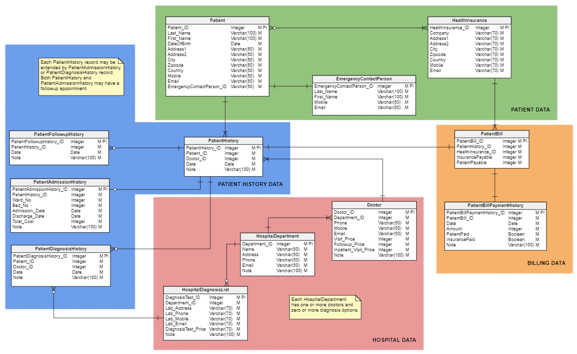
Let’s analyze the cardinalities:
Now that the logical data model is completed, let’s generate the physical data model.
Let’s use Vertabelo to convert the logical database model into the physical database model. Here are 8 things to consider when creating a physical data model.
You can generate a physical data model from a logical data model with just a few steps in Vertabelo:

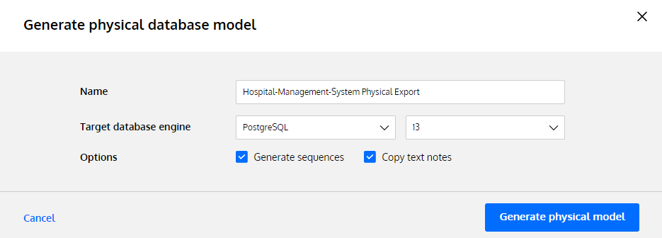
Here comes the physical data model:
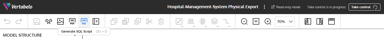
Please note that the generated physical data model comes in a read-only mode by default. To make it editable, click on the Take control button on the top.
As you may notice, the many-to-many relationship between the Patient table and the HealthInsurance table is now implemented via the Patient_HealthInsurance table. Also, the data types are adjusted to the chosen database engine (here, PostgreSQL) – for example, an Integer is now an int. Furthermore, the foreign key constraints are marked in the model.
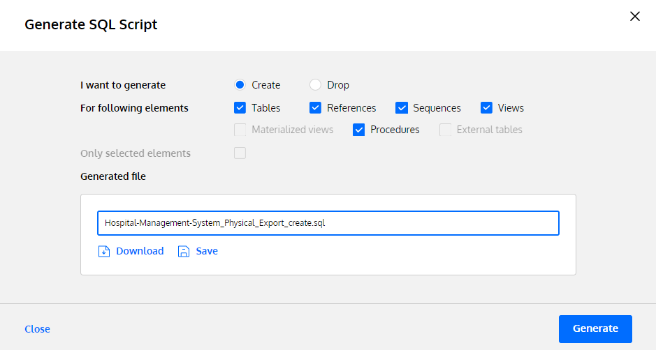
Another handy Vertabelo feature is automatically generating an SQL DDL script for the database model. This script will allow you to import your script and build your physical database. Here is how to do that:
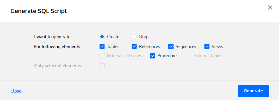
Now you can import this SQL DDL script to create a database. As we created the physical data model for the PostgreSQL database engine, we can import our SQL DDL script into pgAdmin:
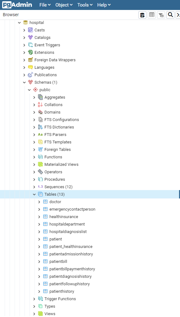
Once that’s done, you’re ready to insert your data.
It is very easy to create your own database with the help of Vertabelo.
You start with an idea of what entities should be included. Then you assign attributes to all entities and define the relationships between them. That’s how you get to the logical data model.
Vertabelo creates a physical data model for you. Furthermore, it can develop an SQL DDL script that can be executed to create your database.
Make sure to try it out yourself.
Subscribe to our newsletter Join our weekly newsletter to be notified about the latest posts. Subscribe